Looking for classes? Ksquare Career Institute, Bengaluru →

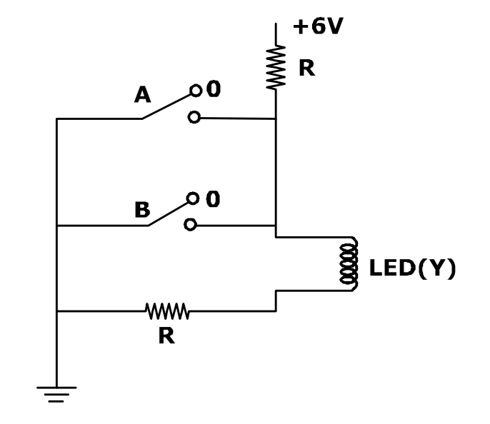
The circuit diagram shown here corresponds to the logic gate,
Detailed Solution
The switches A and B are in parallel across the LED path; closing either switch diverts the current away from the LED. The LED (Y) glows only when both A and B are open (0, 0), which is the truth table of a NOR gate.