Looking for classes? Ksquare Career Institute, Bengaluru →

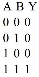
In the following circuit, the output Y for all possible inputs A and B is expressed by the truth table
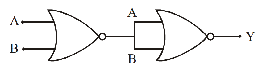
(A NOR gate with inputs A and B is followed by a second NOR gate whose two inputs are joined together.)
Each option lists the rows of the truth table as (A, B, Y).
(A NOR gate with inputs A and B is followed by a second NOR gate whose two inputs are joined together.)
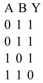
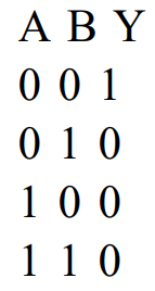
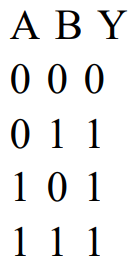
Each option lists the rows of the truth table as (A, B, Y).
A
- 
B
- 
C
- 
D
- 
Detailed Solution
Output of the first NOR gate: $Y' = \overline{A + B}$
This output is fed to both inputs of the second NOR gate. A NOR gate with its two inputs joined acts as a NOT gate: $\overline{Y' + Y'} = \overline{Y'}$
$Y = \overline{Y'} = \overline{\overline{A + B}} = A + B$
So the combination works as an OR gate.
Truth table of $Y = A + B$:
A = 0, B = 0 gives Y = 0
A = 0, B = 1 gives Y = 1
A = 1, B = 0 gives Y = 1
A = 1, B = 1 gives Y = 1
So the truth table is (0, 0, 0), (0, 1, 1), (1, 0, 1), (1, 1, 1).
This output is fed to both inputs of the second NOR gate. A NOR gate with its two inputs joined acts as a NOT gate: $\overline{Y' + Y'} = \overline{Y'}$
$Y = \overline{Y'} = \overline{\overline{A + B}} = A + B$
So the combination works as an OR gate.
Truth table of $Y = A + B$:
A = 0, B = 0 gives Y = 0
A = 0, B = 1 gives Y = 1
A = 1, B = 0 gives Y = 1
A = 1, B = 1 gives Y = 1
So the truth table is (0, 0, 0), (0, 1, 1), (1, 0, 1), (1, 1, 1).