Looking for classes? Ksquare Career Institute, Bengaluru →

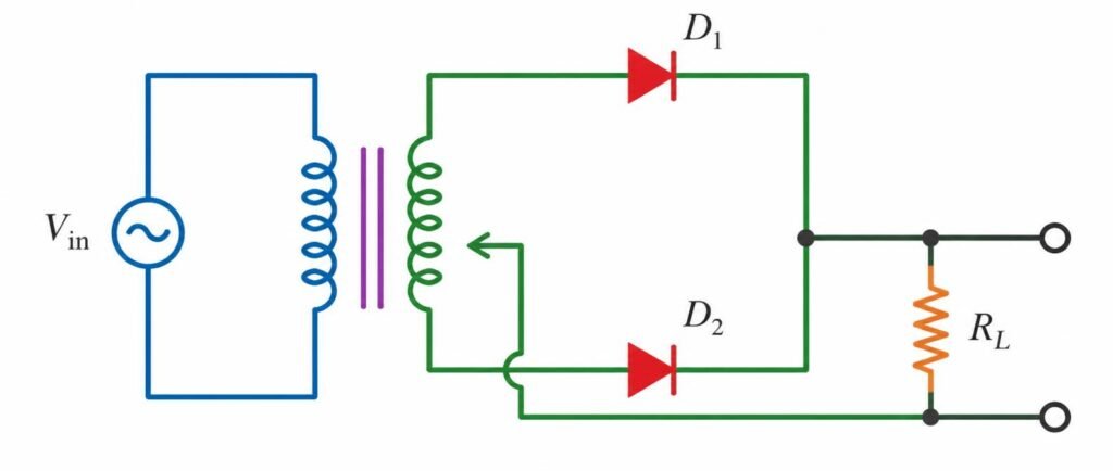
A full wave rectifier circuit with diodes ($D_1$) and ($D_2$) is shown in the figure. If input supply voltage $V_{in} = 220\sin(100\pi t)\text{ volt}$, then at $t = 15\text{ m sec}$:
A
$D_1$ is forward biased, $D_2$ is reverse biased
B
$D_1$ is reverse biased, $D_2$ is forward biased
C
$D_1$ and $D_2$ both are forward biased
D
$D_1$ and $D_2$ both are reverse biased
Explanation
At $t = 15\text{ ms}$, phase is $1.5\pi$ radians where sine is negative ($-1$). This negative half-cycle makes $D_1$ reverse biased and $D_2$ forward biased.
Detailed Solution
Evaluating input voltage at $t = 15\text{ ms} = 0.015\text{ s}$: $V_{in} = 220 \sin(100\pi \times 0.015) = 220 \sin(1.5\pi) = 220(-1) = -220\text{ V}$. Since the AC input is in its negative half-cycle, the secondary transformer winding has a negative potential at the top (anode of $D_1$) and a positive potential at the bottom (anode of $D_2$) relative to the center tap. Consequently, diode $D_1$ is reverse biased and diode $D_2$ is forward biased.