Looking for classes? Ksquare Career Institute, Bengaluru →

p-n junction diode
Appears in
Concepts tested here
- Barrier potential in a circuit
- Forward and reverse bias
- Forward and reverse biased diodes
All Questions
2015 AIPMT-II 1 question
-
In the given figure, a diode D is connected to an external resistance R = 100 $\Omega$ and an e.m.f of 3.5 V. If the barrier potential developed across the diode is 0.5 V, the current in the circuit will be:
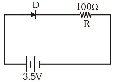 Potential difference across R = 3.5 − 0.5 = 3.0 V
$i = \frac{V}{R} = \frac{3}{100} = 30$ mA
2012 AIPMT-PRE 1 question
-
Two ideal diodes are connected to a battery as shown in the circuit. The current supplied by the battery is
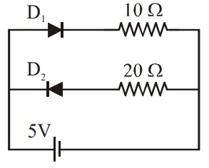 $D_1$ (in series with 10 $\Omega$) is forward biased and conducts; being ideal it has zero resistance.
$D_2$ (in series with 20 $\Omega$) is reverse biased and does not conduct.
So current flows only through the 10 $\Omega$ branch: $i = \frac{5}{10} = 0.5$ A
2011 AIPMT-MAINS 1 question
-
In the following figure, the diodes which are forward biased are
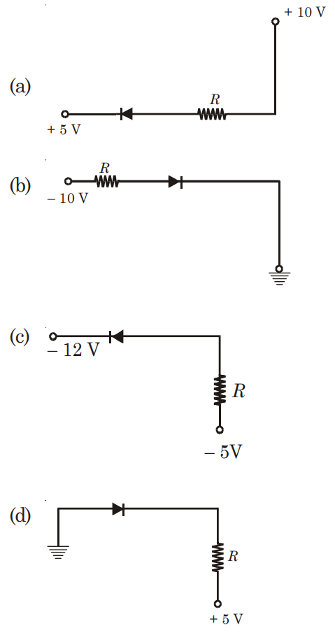 A diode is forward biased when its p-side (anode) is at a higher potential than its n-side (cathode).
(a): the p-side is connected (through R) to +10 V and the n-side to +5 V; p is at the higher potential, so it is forward biased.
(b): the p-side is connected (through R) to −10 V and the n-side to earth (0 V); p is at the lower potential, so it is reverse biased.
(c): the p-side is connected (through R) to −5 V and the n-side to −12 V; −5 V is higher than −12 V, so it is forward biased.
(d): the p-side is earthed (0 V) and the n-side is connected (through R) to +5 V; p is at the lower potential, so it is reverse biased.
Hence the forward biased diodes are (c) and (a).